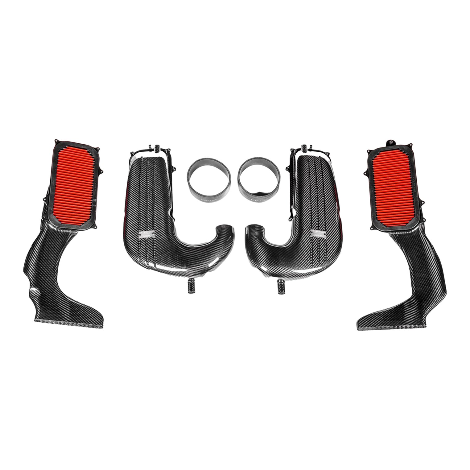
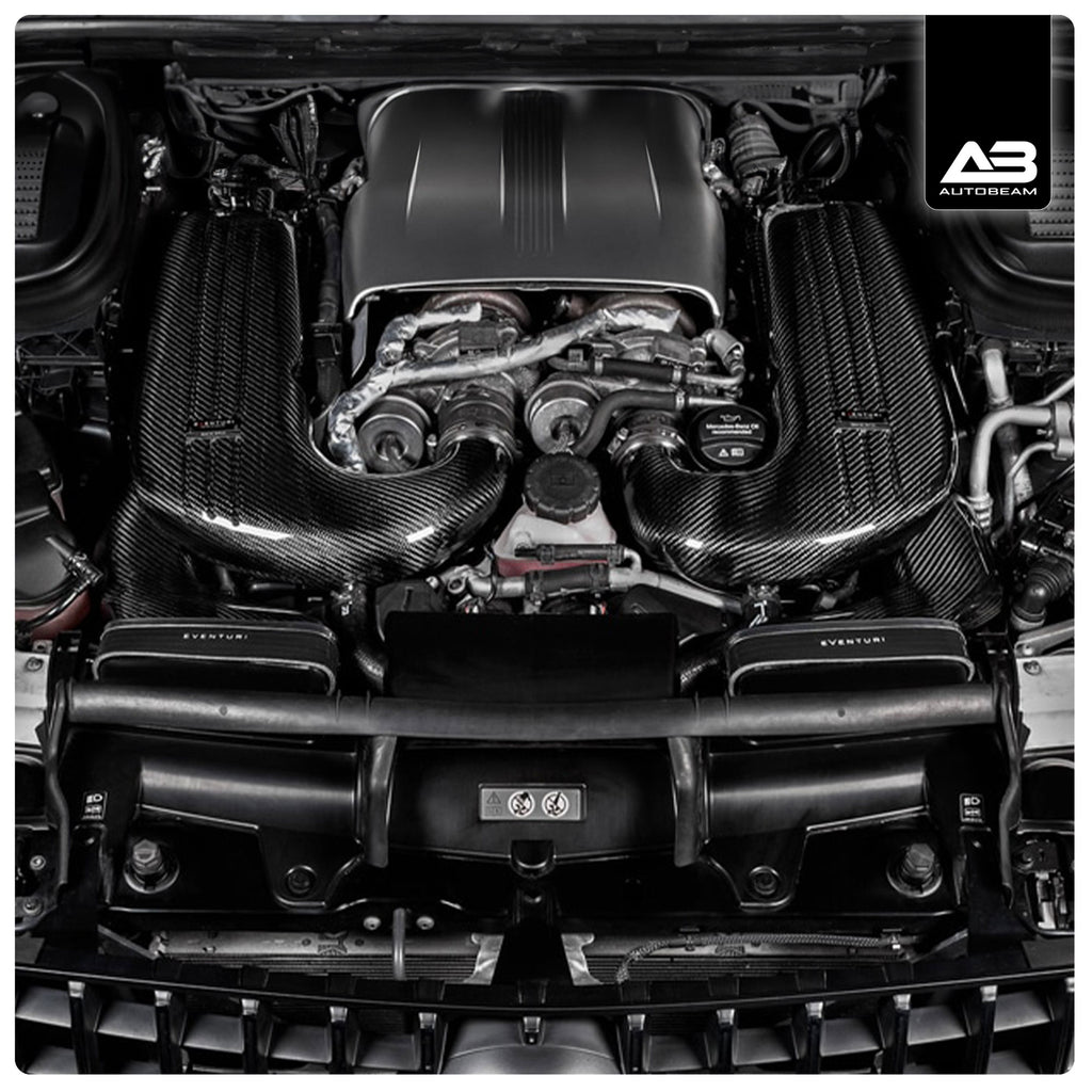
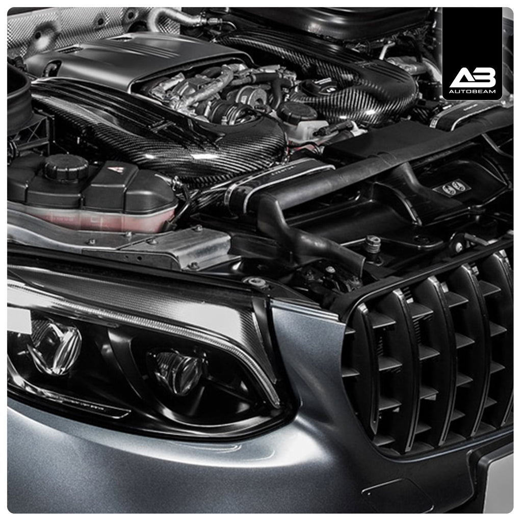
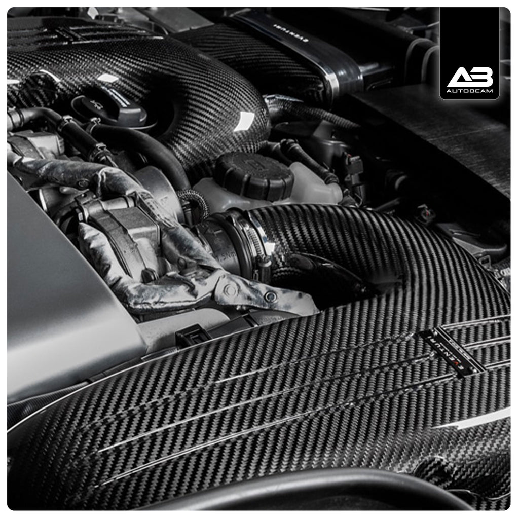
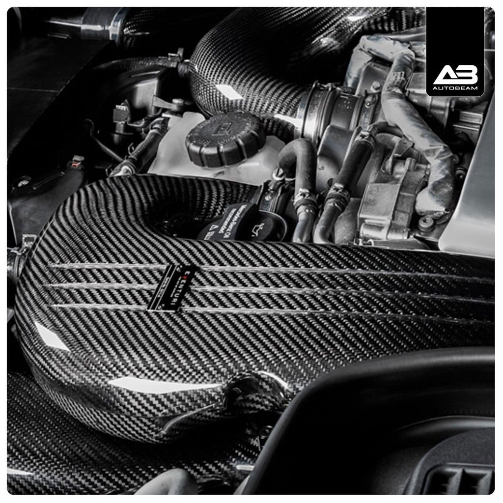
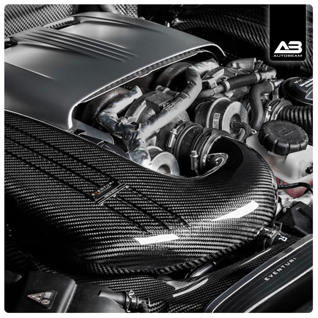
With all 3 objectives met, our W205 C63S intake system delivers on all fronts and allows for the turbos to generate boost more efficiently. This results in an improved throttle response and genuine power gains which increase with higher states of tune.
|
- Information
- Fitment
- What's in the box
- Shipping
- Reviews
The Mercedes GLC63S AMG intake system is the culmination of extensive development and testing. Our design brief consisted of 3 main objectives: 1) Increased flow rate. 2) Low intake temperatures. 3) Smooth airflow. The first objective was met by utilising all of the limited space available in the GLC63S engine bay resulting in a 39% higher flow rate over the stock system. The second objective was met by designing a fully sealed system. The GLC63S engine bay reaches high temperatures with heat sources like the turbos in close proximity to the intake so it is crucial that the intake remains sealed. The final objective was met by designing an organically shaped system with custom rounded panel filters to ensure the airflow path contained no sharp corners and therefore allowed for the flow to remain laminar. With smooth transitions from the filters to the turbo inlets, our intake minimises the formation of turbulence and therefore the turbos are able to operate more efficiently.
The airbox assemblies consist of the upper and lower sections which are separated by the filter panels. Each section has been meticulously designed for maximum internal volume whilst ensuring a smooth path for airflow to travel to the turbos. The most challenging aspect of this design was to increase the internal volume of the airboxes in an attempt to increase the flow rate capacity over the stock airboxes. Since the GLC63S engine bay is so tightly packed, this was only achievable by maximising the total internal height of the airboxes. The biggest increase came from enlarging the upper airbox lids. As can be clearly seen, we have managed to achieve a significant increase in volume while also providing a smoother airflow path.
Looking at the side profile comparison between the stock and the Eventuri airboxes with the front duct sections removed, it is clear that the stock airbox has a restricted space for airflow after the filter in the upper section. It narrows down to just 23mm in height whereas in comparison, the Eventuri system achieves a height of 56mm which is 143% larger than stock. The stock airbox also has a large area on the top section which is taken up by the MAP sensor. This area is taken away from the internal volume and therefore causes another restriction. We have relocated the sensors to the back of the upper sections allowing the full volume above the filters to be useable for airflow. Another consideration is the inlet to the lower airbox which on the stock system has a flexible convoluted section with multiple ridges at 43mm in height. Our system removes these ridges for a smoother entry and increases the height to 74mm.
The front view of the airboxes with the duct sections removed clearly show how restricted the stock version is. With the upper section narrowing down to just 23mm across a large section, airflow is significantly restricted. In comparison our airbox maintains a much larger area to the turbo inlets. The inlet to the lower section has also been significantly increased in area. The Eventuri inlet is approximately 84% larger in cross sectional area compared to stock.
To achieve optimum airflow we designed custom panel filters which have a double filtration layer of ISO 5011 tested non-woven mesh. The filtration medium is dry so does not require oil which can harm sensitive flow sensors. In addition, we designed them to have a rounded outer profile rather than the traditional rectangular shape which has sharp 90 degree corners. This allowed us to maintain a smoother airbox profile which has no sharp corners thus minimising the onset of turbulence in the flow path.
A crucial consideration when using panel filters is to ensure that they are properly sealed inside the airboxes at all times. Since we are using prepreg carbon fibre for the airboxes, we could not rely on the relatively large tolerance of carbon construction in comparison to a precision machined component. Therefore we designed flanges CNC machined from a single billet of aluminum and black anodised, which the filters sit inside. These flanges are mounted inside the carbon airboxes and provide a reliable and accurate seal around the rubber profile of the filters.
To hold the airboxes in place we use the stock rubber bushes and to hold these bushes we have CNC machined the holders for an exact and secure fitment.
We conducted some flow rate tests using a Superflow SF-1020 to measure the maximum flow rate possible at a pressure drop of 28” H2O. Tests were done on the same day in controlled conditions using the same test jig for each system. We tested our sealed intake with our custom filter, the stock airbox with stock filter and an open cone tubular type intake with the intake tube at the same diameter as the stock turbo inlet. Both the left and right side airboxes were tested.
This shows just how restrictive the stock airbox is, which we have managed to improve by up to 41% in maximum possible flow rate. Interestingly the open cone intake, although flowed more than stock, did not flow more than our sealed system. This is because the diameter of the intake tube remains constant all the way from the outlet of the turbo to the cone. So whereas our system dramatically opens in internal volume from outlet to the filter, the open cone system remains at the same smaller cross sectional area. It’s like sucking through a straw vs sucking through a funnel.

2 x Carbon Fibre Airbox Lids with Turbo Inlet Transitions
2 x Carbon Fibre Airbox Bases with Inlet Duct Transitions
2 x Bespoke High Flow Panel Filters
2 x CNC Machined Stainless Steel Inlet Flanges
4 x CNC Machined Aluminium Filter Flanges
2 x CNC Machined MAP Bosses
4 x CNC Machined Rubber Mount Holders
Laser Cut Stainless Steel Bracket Work
Autobeam | Autoprint | Auto Finesse
Orders placed before 1pm
Processed & shipped the same day unless otherwise stated.
Orders placed after 1pm
Processed & shipped the next working day.
Orders placed after 1pm on a Friday.
Processed & shipped the following Monday.
Orders are shipped Monday-Friday only.
All other brands
In stock items normally delivered within 1-3 days. Items made to order can be upto several weeks.
Stock for all other brands are not monitored therefor may be out of stock.
Information
The Mercedes GLC63S AMG intake system is the culmination of extensive development and testing. Our design brief consisted of 3 main objectives: 1) Increased flow rate. 2) Low intake temperatures. 3) Smooth airflow. The first objective was met by utilising all of the limited space available in the GLC63S engine bay resulting in a 39% higher flow rate over the stock system. The second objective was met by designing a fully sealed system. The GLC63S engine bay reaches high temperatures with heat sources like the turbos in close proximity to the intake so it is crucial that the intake remains sealed. The final objective was met by designing an organically shaped system with custom rounded panel filters to ensure the airflow path contained no sharp corners and therefore allowed for the flow to remain laminar. With smooth transitions from the filters to the turbo inlets, our intake minimises the formation of turbulence and therefore the turbos are able to operate more efficiently.
The airbox assemblies consist of the upper and lower sections which are separated by the filter panels. Each section has been meticulously designed for maximum internal volume whilst ensuring a smooth path for airflow to travel to the turbos. The most challenging aspect of this design was to increase the internal volume of the airboxes in an attempt to increase the flow rate capacity over the stock airboxes. Since the GLC63S engine bay is so tightly packed, this was only achievable by maximising the total internal height of the airboxes. The biggest increase came from enlarging the upper airbox lids. As can be clearly seen, we have managed to achieve a significant increase in volume while also providing a smoother airflow path.
Looking at the side profile comparison between the stock and the Eventuri airboxes with the front duct sections removed, it is clear that the stock airbox has a restricted space for airflow after the filter in the upper section. It narrows down to just 23mm in height whereas in comparison, the Eventuri system achieves a height of 56mm which is 143% larger than stock. The stock airbox also has a large area on the top section which is taken up by the MAP sensor. This area is taken away from the internal volume and therefore causes another restriction. We have relocated the sensors to the back of the upper sections allowing the full volume above the filters to be useable for airflow. Another consideration is the inlet to the lower airbox which on the stock system has a flexible convoluted section with multiple ridges at 43mm in height. Our system removes these ridges for a smoother entry and increases the height to 74mm.
The front view of the airboxes with the duct sections removed clearly show how restricted the stock version is. With the upper section narrowing down to just 23mm across a large section, airflow is significantly restricted. In comparison our airbox maintains a much larger area to the turbo inlets. The inlet to the lower section has also been significantly increased in area. The Eventuri inlet is approximately 84% larger in cross sectional area compared to stock.
To achieve optimum airflow we designed custom panel filters which have a double filtration layer of ISO 5011 tested non-woven mesh. The filtration medium is dry so does not require oil which can harm sensitive flow sensors. In addition, we designed them to have a rounded outer profile rather than the traditional rectangular shape which has sharp 90 degree corners. This allowed us to maintain a smoother airbox profile which has no sharp corners thus minimising the onset of turbulence in the flow path.
A crucial consideration when using panel filters is to ensure that they are properly sealed inside the airboxes at all times. Since we are using prepreg carbon fibre for the airboxes, we could not rely on the relatively large tolerance of carbon construction in comparison to a precision machined component. Therefore we designed flanges CNC machined from a single billet of aluminum and black anodised, which the filters sit inside. These flanges are mounted inside the carbon airboxes and provide a reliable and accurate seal around the rubber profile of the filters.
To hold the airboxes in place we use the stock rubber bushes and to hold these bushes we have CNC machined the holders for an exact and secure fitment.
We conducted some flow rate tests using a Superflow SF-1020 to measure the maximum flow rate possible at a pressure drop of 28” H2O. Tests were done on the same day in controlled conditions using the same test jig for each system. We tested our sealed intake with our custom filter, the stock airbox with stock filter and an open cone tubular type intake with the intake tube at the same diameter as the stock turbo inlet. Both the left and right side airboxes were tested.
This shows just how restrictive the stock airbox is, which we have managed to improve by up to 41% in maximum possible flow rate. Interestingly the open cone intake, although flowed more than stock, did not flow more than our sealed system. This is because the diameter of the intake tube remains constant all the way from the outlet of the turbo to the cone. So whereas our system dramatically opens in internal volume from outlet to the filter, the open cone system remains at the same smaller cross sectional area. It’s like sucking through a straw vs sucking through a funnel.
Fitment

What's in the box
2 x Carbon Fibre Airbox Lids with Turbo Inlet Transitions
2 x Carbon Fibre Airbox Bases with Inlet Duct Transitions
2 x Bespoke High Flow Panel Filters
2 x CNC Machined Stainless Steel Inlet Flanges
4 x CNC Machined Aluminium Filter Flanges
2 x CNC Machined MAP Bosses
4 x CNC Machined Rubber Mount Holders
Laser Cut Stainless Steel Bracket Work
Shipping
Autobeam | Autoprint | Auto Finesse
Orders placed before 1pm
Processed & shipped the same day unless otherwise stated.
Orders placed after 1pm
Processed & shipped the next working day.
Orders placed after 1pm on a Friday.
Processed & shipped the following Monday.
Orders are shipped Monday-Friday only.
All other brands
In stock items normally delivered within 1-3 days. Items made to order can be upto several weeks.
Stock for all other brands are not monitored therefor may be out of stock.
Reviews


